DWH Technical Topic: Block diagrams
By Clarence Klassen, P. Eng.
As an engineer, I like to work with block diagrams. I look for a block diagram in the detailed user manual for a drive. Sometimes I do not find one.
The best are about 10 pages long and show all relevant signals used in the drive regulators and setpoints used to control the drive. The very best projects display the block diagram in the drive software with live values. Honestly, who wants to read a 750-page user manual with no diagrams? Follow this with a call to tech support, because some critical piece of information is vaguely described, or translated in a way to make it meaningless.
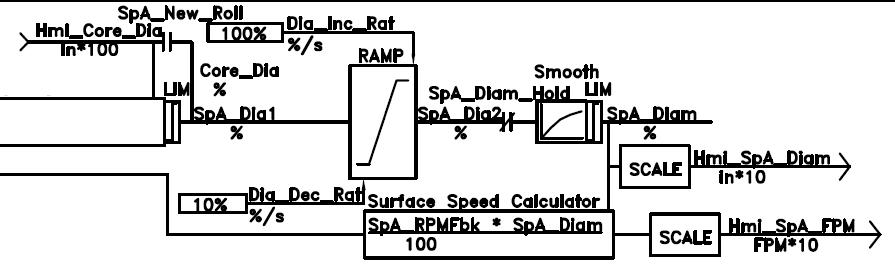
Then for web-handling, a project-specific block diagram showing the control of the system is hard to live without. The diagram will require at least one page per machine section. It will show signal names, units, signal flow, major functions, and signals communicated between controllers and drives. Is speed in RPM, fpm, mpm, or % -- what does % mean?
The diagram will also show in which piece of equipment each function is performed. Is the tension regulator in the controller or the drive? Is the diameter calculated in the controller or the drive?
The time to produce a block diagram is before the coding begins.
I am surprised at how often the equipment owner will misplace a block diagram even when one has been carefully produced.